|
ENGLISH ELECTRIC TYPE 1
FRAME No. 1
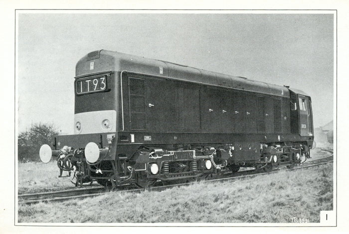
GENERAL DESCRIPTION
This frame shows an ENGLISH ELECTRIC Type 1 diesel-electric locomotive.
The wheel arrangement is B-B; (i. e. the locomotive has two bogies, each of which has two individually-driven axles).
The locomotive may be operated singly, or may be coupled, to form a two-unit or a three-unit locomotive, with other locomotives which carry the 'blue star' coupling symbol.
An Old locomotive has, at the front and at the rear end, two red tail lights and four white marker lights. The marker lights have white marker discs. A New locomotive, however, has two red taillights and a route indicator at each end, but has no marker lights.
A New locomotive has automatic brake adjusters, which an Old locomotive has not.
GENERAL DATA
Weight in running order: 72 tons
Number of traction motors:4
Continuous tractive effort:
New loco: 25,000 Ib at 11.0 mile/h
Old loco: 19,000 Ib at 14.8 mile/h
Length over buffers: 46ft 9 3/8 inches,
Height:12ft 7, 5/8in, Width:8ft 9in.
Wheelbase:32ft 6in, Wheelbase of one bogie: 8ft 6in
Distance between bogie centres:24ft Oin
Minimum curve negotiable: 3. 5 chains radius
Wheel diameter, (new):3ft 7in
Total fuel capacity: 400 gal
Total capacity of sand boxes: 7,1/2 cu ft
Maximum permitted speed: 75 mile/h
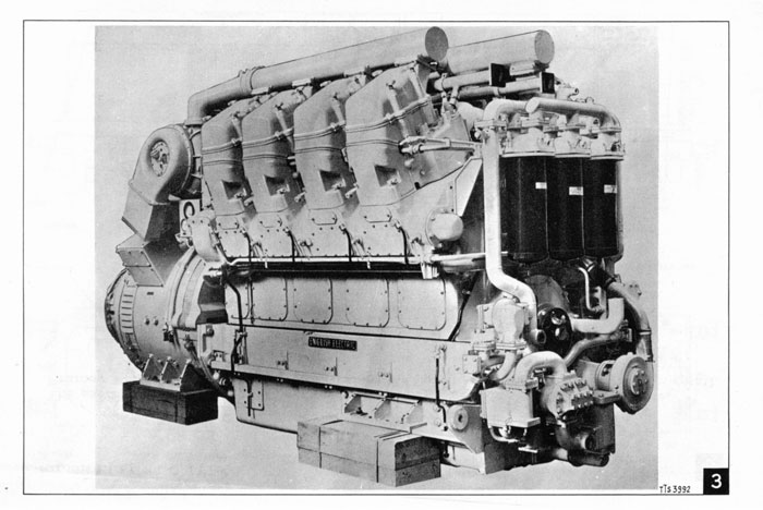
ELECTRICAL MACHINES
MAIN GENERATOR Type EE819/3C;
(6-pole, self-ventilated, separately-excited, d. c. machine)
Rating (continuous) Old Loco 1070A 600V 642kW at 850 rev/min New Loco 1200A 537V 645kW at 850rev / min
AUXILIARY GENERATOR Type EE911/2B;
(8-pole, self-excited, d. c. machine, overhung. Ventilated by fan of main generator) Rating (continuous) 436A 110V 48kW at 850 rev/min
TRACTION MOTORS Type EE526/5D for Locomotives Type EE526/BD for Locomotives and Both these traction motors with a continuous rating of:
DBOOO to DB049 DB050 to DBl99 DB300 to DB327 are 6-pole, series-wound, force-ventilated, 600A 300V 212 hp at 362 rev / min
D.C.MACHINES:
BLOWER MOTORS Type EE750/ 10G; (2-pole, series-wound, self-ventilated, d. c. machines) Rating (continuous) 94A 110V II hp at 2550 rev/min
EXHAUSTER MOTOR Type EE755/ lA for Old locomotives (4-pole, shunt-wound, self-ventilated, d. c. machine) Rating (continuous, full-field) 59A 110V B hp at 900 rev/min Type EE762/6D for New locomotives (4-pole, shunt-wound, d. c. machine) Rating (continuous, full-field) 49A 110V 5.25 hp at 900 rev/min
LUBRICATING-OIL -PRIMING -PUMP MOTOR Type TFZ97924; (2-pole, compound-wound, totally-enclosed, d. c. machine) Rating (i hour) llA 110V 1.25 hp at 1900 rev/min
FUEL-SUPPLY-PUMPMOTOR Type TFZ97915; (2-po1e, compound-wound, tota11y-enc1osed, d. c. machine} Rating (continuous} 1.4A 110V 0.125 hp at 1420 rev/min
LOAD-REGULATOR MOTOR Type TFZ97900; (2-po1e, series-wound, sp1it-fie1d, tota11y-enc1osed, d. c. machine} Rating (continuous} 0.68A 110V 0.4 hp at 220 rev/min
|